GENERAL AND APPLICATION:
KYN28-12 model Metal-clad Centered Metal-enclosed Switchgear (switchgear for short hereunder) is a new product independently designed and developed by HEAG Group after absorbing international advanced technology, which can replace the old model metal-enclosed switchgears, such as KYN1-10, JYN2-10, GFC-10, etc. The product has obvious advantages as follows:
1.1 The enclosure is completely formed by Al-Zn coated steel plate after multiple bending processed by CNC machine, and then is assembled with bolts, which has strong mechanical strength and effectively assure the neatness and good appearance.The door is painted by plastic powder and has strong anti-impact and corrosion proof ability. The protection grade of enclosure is IP4X.
1.2 The main circuit breaker can be VD4 model VCB (ABB), C3 series fixed type LBS or VS1,ZN73 model VCB produced by HEAG group, or some homemade VCBs (e.g. VK, ZN21).
1.3 For circuit breaker, the air insulation distance shall be over 1 25mm, and the composite insulation shall be over 60mm. All VCBs has unique advantages of long life, high relia bilit, less maintenance and small size. The switchgear applies to three phase power system of rated voltage 3.6~12kV AC 50Hz for receiving and distributing power energy,and also for circuit control, monitor and protection. It can be used in single- busbar
system, single-busbar sector system or double-busbar system. The switchgear accords with standards of IEC 298, IEC 694, GB3906 and DIN. VDE 0670 and so on. Furthermore, it has perfect and reliable anti-misoperation function.
NORMAL SERVICE CO NDITIONS:
◇ Environmental ambient temperature: +40°C~-10°C;
◇ Altitude above sea level: not exceeding 1000m;
◇Earthquake intensity: not exceeding 8 degree;
◇Average relative humidity(monthly):≤90%;
◇Average relative humidity(daily):≤95%;
◇Installation site: without fire risk, explosion hazard, heavy pollution,chemical corrosion and violent vibration.
◇Otherwise, the service conditions shall be negotiated.
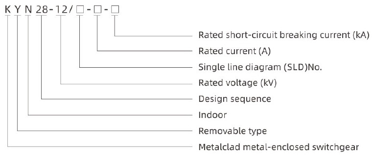
MODEL AND MEANING:
 MAIN TECHNICAL PARAMETERS:
4.1 Main technical parameters of switchgear
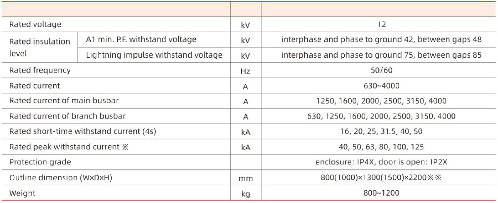
※: The short-circuit capacity of CT shall be separately considered;
※※: The width of switchgear shall be 800mm at rated short-time withstand current up to 31.5kA and rated current of branch busbar up to 1250A, and it shall be 1000mm
when rated short-time withstand current is 4QkA or above and rated current of branch busbar is above 1250A.The depth shall be selected by the user.
4.2 Main technical parameters of VS1, VD4 model VCB
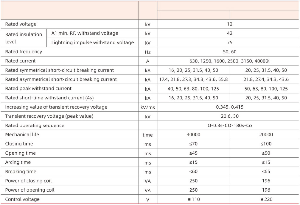
As circuit breaker is used to control3.6~12kV motor and starting current is less than 600A, metal oxide lightening arrester must be aded, and the user shall discuss with the manufacturer about the detail requirements. As circuit breaker is used to break capacitor bank and rated current of the capacitor bank doesn't exceed 80% of that of circuit breaker.
※Air-cooled device must be added when rated current is up to 3150A.
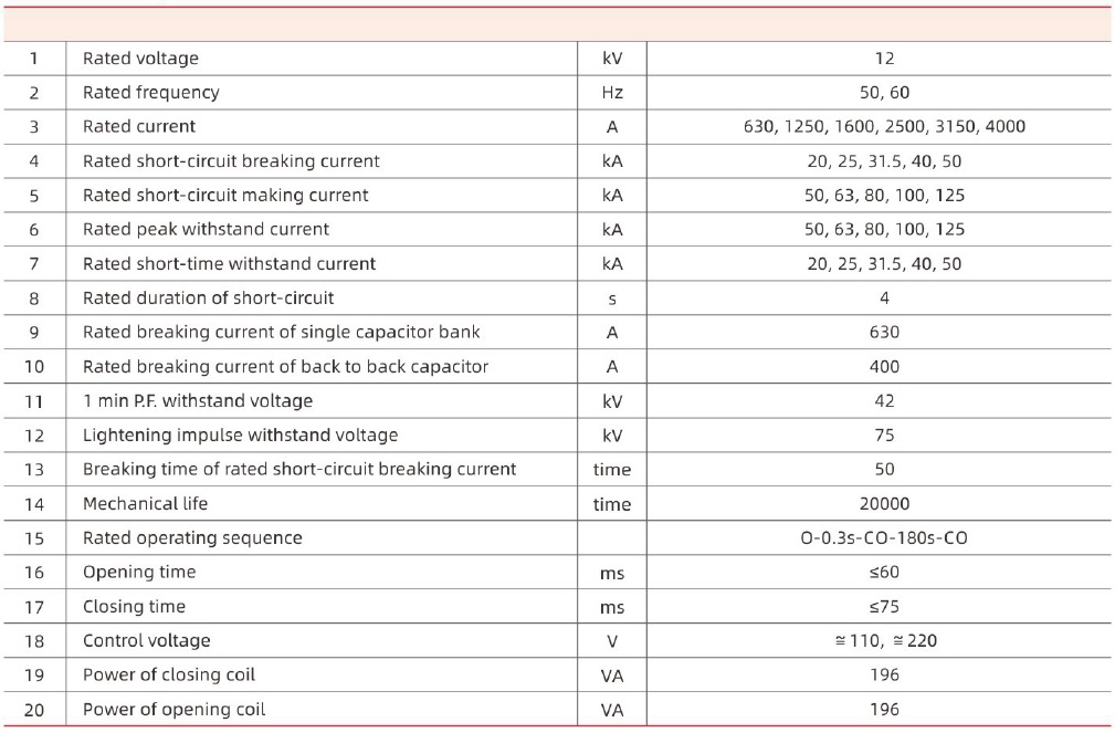
4.3 Main technical parameters of ZN73-12 model VCB
 NTERNAL ARC FAULTTEST:
The design of switchgear has the accident influence of internal arc fault and it has been strictly tested.
PRODUCT STRUCTURE:
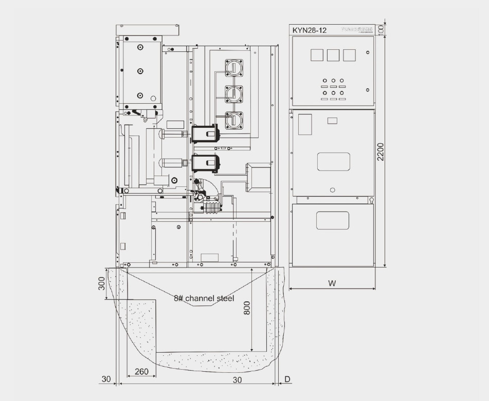
The product structure as per Fig.1.
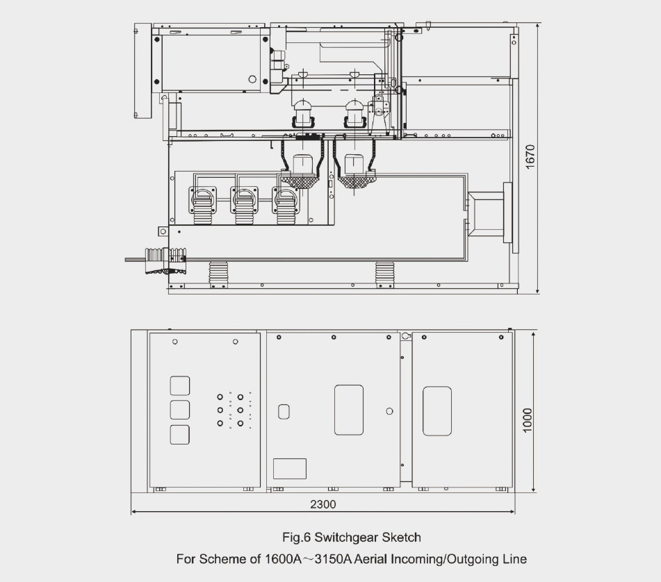
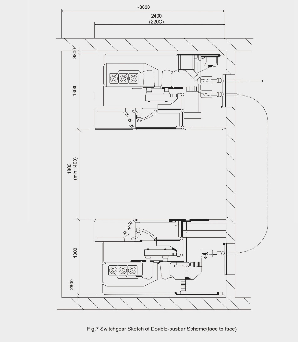
The switchgear consists of a fixed body and a drawable part (handcart for short). The enclosure and all the metal separating plates of each function unit are joined with bolts. The electrical components in cubicle show as Fig.1. The protection grade of enclosure is IP4X and it will be IP2X as the cubicle door is opened. The cubicle can collocate with VCB hand cart or fixed load switch. It can be made in overlapped arrangement, which means face to face or back to back in double-row (see Fig.5 & 6).
6.2 Handcart
The handcart frame is made of steel sheet processed by CNC machine and is assembled with rivet. According to its usage , the handcart can sort into CB handcart, PT handcart, measuring handcart and so on. The height and depth of different kinds are same, so they are interchangable if only same specification. The handcarts has isolating/ testing position and working position in cubicle, each position is equipped with a locating device to ensure that the handcart will not move at random when in specified position. Unlock the position lock before move the handcart, and open CB before move CB handcart.
6.3 Compartments in cubicles
6.3.1 CB compartment
A special guide rail is installed in CB compartment (B) for the handcart to move between isolating/testing position and working position. The movable curtain plate (12) made of metal sheet is installed on the back wall of handcart compartment. When the handcart moves from isolating/testing position to working position, the curtain plate in front of fixed contact (4) will automatically open. Contraril,it will automatically close to seal the fixed contact box, thereby to guarantee the operator's safety. If the handcart is operated when the cubicle door is closed, its position can be seen through observing window. Meanwhile, ON/OFF buttons, ON/OFF mechanical position
indicator and energy storing/releasing indicator can also be seen.
6.3.2 Draw-out type CB handcart
The handcart frame is made of steel plate, VCB and other auxiliary equipments are mounted on it. Primary movable contac (5) with spring finger contact system can be mounted on the outgoing terminals of CB through the arm rod, and the ON/OFF position indicator and control buttons of operating mechanism are mounted on the handcart's panel for convenient operation. When the handcart enters into the cubicle and reaches the isolating/testirg position, the handcart's case reliably connects with the earthing system, and the instrument protection and control circuits are also connect the cubicle through the secondary plug (10). However, when the handcart reaches the working position, primary circuit will be connected except CB.
6.3.3 Busbar compartment
The busbar (3) is led from one cubide into another cubicle under the supporting of insulation bushing, and connects with the fixed contact box through the branch busbar (2). The main busbar and inter busbar are round copper bars with rectangular section. It can be arranged for double busbar in parallel under large current load, and all busbar are covered with heat -shrinking tube. Full-insulation busbar system consumedly decreases the occurrence probability of the internal faults. Further more, the busbar compartment is isolated from each other. When internal faults occur in one cubicle, the dissociate gas will not enter into the next cubicle to void expanding the faults.
6.3.4 Cable compartment
CT (7), PT (8) and the earth swith (6) can be mounted on the back wall of cable compartment, and lighting arrester can be mounted inside it. After the handcart (3) and level separating plate (9) are removed, the worker can enter into cubicle to install the cables from face.There are specified cable conductors for connecting 1~6PCS single- core cables in parallel in cable compartment. A movable metal plate can be mounted on the bottom to provide convenience.
6.3.5 Instrument compartment
The instrument compartment includes relay protection components, meters, power indicator and specified secondary equipments.The control circuits are laid in the neck grave with sufficient space and metal cover plate. The left one is pre-reserved for outgoing and incoming of the secondary busbar, and secondary circuits are laid in the right one. There re also leading holes for secondary busbar on the side plate of the instrument compartment.
6.4 Interlocking device for preventive mal-operation
The cubicle has reliable interlocking device for protecting the operators and equipments. Details are as following:
6.4.1 When the handcart moves from working position to isolating/testing position, the movable curtain plate will seal the fixed contact box to avoid entering into the electrified compartments. At the time of overhaul, please lock the curtain plate by hang-lock.
6.4.2 When CB is in closing position, the handcart can't be pulled out from working position or moved from isolating/testing position to working position; CB can be operated only when the handcart is completely locked in the testing or working position.
6.4.3 Earth switch can be operated only when the handcart is in isolating/testing position or outside the cubicle. When earth switch is in closing position, the handcart can't be pushed from isolating/testing position to working position.
6.4.4 When the handcart is in working position, secondary plug is locked and can't be pulled out.
6.5 Pressure-releasing device
The pressure-releasing devices are respectively mounted on the top of handcart compartment, busbar compartment and cable compartment. When internal fault arc occurs to CB or busbar, the air pressure will increase accompanying the appearance of arc, then the metal pressure-releasing plate will be automatically opened to release gas and pressure to ensure the safety of operators and cubicle.
6.6 Position interlocking between secondary plug and the handcart
The connection between secondary circuit of the cubicle and the handcart's secondary circuit is realized through secondary plug.Moving contact lead of secondary plug, covered with a nelon bellows, can be connected with the handcart, and secondary fixed contact socket is mounted on the right-top of CB compartment. Secondary plug can be connected or released only when the handcart in testing/ isolating position, however, when handcart in working position, secondary plug will be locked and not be released.
6.7 Power indicator
The power indicator mounted in the cubicle consists of HV sensor and portable display. The sensor is mounted at the side of busbar or feeder, and the display is mounted on the door of instrument compartment. When check if A, B, C phase is electrified, press the button,if it acts, it means the busbar or feeder is electrified, otherwise, they aren't electrified.
FOUNDATION R EFERENCE:
7.1 All the construction of the cubicle's installation foundation should accords with related provisions of "Technical Specifications for Power Construction and Acceptance".
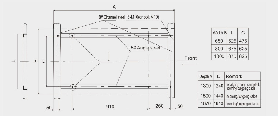
7.2 The installation foundation consists of structure parts, such as angle steel, square steel and channel steel. The height of concrete shall be 1~3mm lower than structure parts. The unevenness of installation foundation shall be less than 2mm.
7.3 Foundation structure as per Fig.3.
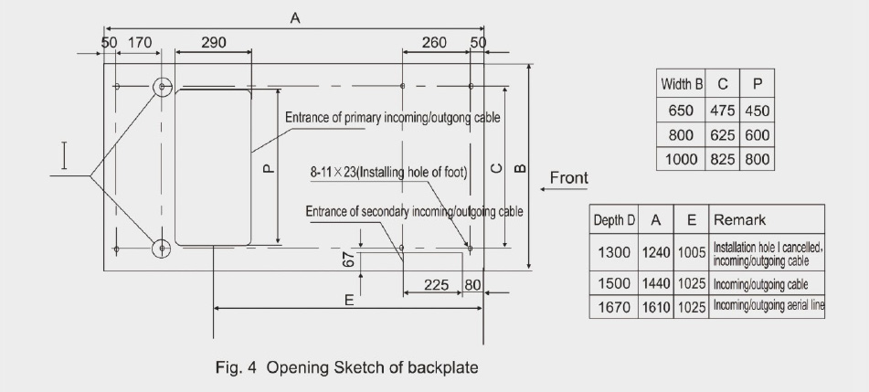
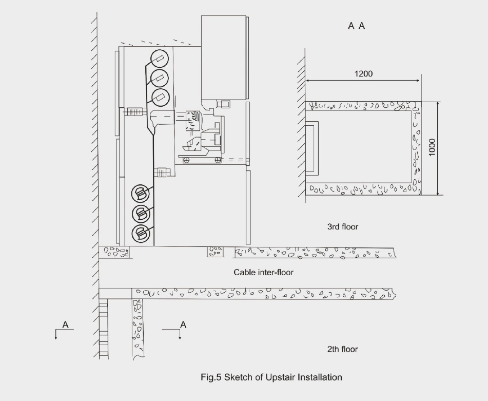
7.4 Upstair layers with cables as per Fig.4.
INSTALL ATION:
8.1 According to the requirements and drawings, the cubicles shall be carried to the specified site. Arrangement shall be started from the middle if the arrangement is long (over 10 sets).
8.2 Specified transportation means (e.g. crane or forklift) are valid, cylinder and crowbar prohibited.
8.3 Keep the CB handcart in another place separated from cubicle.
8.4 Loose the fixed bolts in front of busbar compartment, and remove the vertical separating plate (9).
8.5 Loose the fixed bolts of the level separating plate (19) on the bottom of CB compartment and remove it.
8.6 Loose and remove the floor plate (16).
8.7 Remove cover plate (1, 2) of control channel from the left side of cubicle and the right-left one at the same time.
8.8 Install the cubicle one by one on the foundation including both vertical and horizontal sides. The maximum gap shall not exceed 2mm through adjustment.
8.9 After the arrangement, the cubicle can be connected with foundation channel steel with foot screw.
INSTALL ATION OF BUS AND CABLE:
9.1 Installation of busbar:
1) Install busbar bushing.
2) Clean the busbar with a dean and dry soft coth, and check if the insulation bushing is damaged, paint conductive grease plaster or neutral vaseline to the joints.
3) Install busbar one by one, and connect main busbar with corresponding branch busbar according to Fig.2.
9.2 Installation of cable
1) According to primary scheme and secondary scheme, connect cables in these specified positions (in clause 6.3.4/6.3.5)
2) Block all the cable holes.
EARTHING DEVICE:
10.1 Connect all the main earthing busbar together by the connection plate.
10.2 Connect all the earthing leads inside the cubicle.
10.3 Connect the earthing wire of earthing switch with main earthing bus (18) of the cubicle.
10.4 Connect the main earthing busbar of cubicle with earthing network.
OPERATION REFER ENCE:
11.1 Lift draw-out type CB onto the service handcart by suitable crane and lock it tightly.
11.2 Adjust the height of service handcart to make it reliably connect with the cubicle.
11.3 Handcart reaches testing position: When CB is in opening state, pull locking plate by hands to make lock tongue retract into bottom board machine till going into testing position of guide rail. (Attention: Prohibit pulling the tripping spanner of service handcart,otherwise, the service handcart will leave the cubicle body and CB falls to ground and is damaged.) and both left and right lock tongues are inserted into the lock hole.
11.4 Insert 58 pin aerial plug into secondary circuit socket of the cubicle, and close CB door, then begin the test.
11.5 Handcart reaches working position: When CB is in opening state, insert the special handle into the forward machine of bottom board machine, and rotate the handle in counter-clockwise to make CB reach working position, then put down the handle and start the ON/OFF operation.
11.6 Handcart quits working position: When CB is in opening state, insert the special handle into the rocking in mechanism of bottom board machine, and rotate the handle anticlockwise to make CB reach testing position, then open the door of CB compartment and pull out secondary plug.
11.7 Lock the service handcart with cubicle body tightly, pull the bottom locking plate by hands to make lock tongue retract into bottom board machine, then quit CB out of cubicle and carry it to the service handcart.
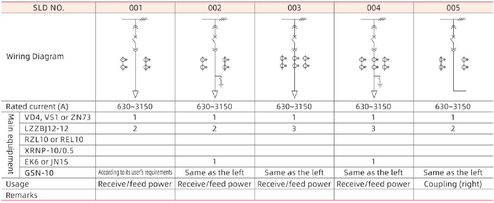
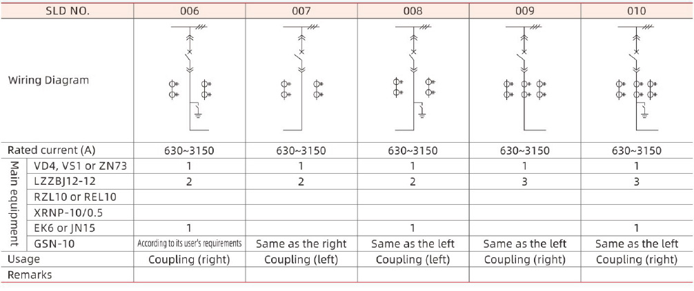
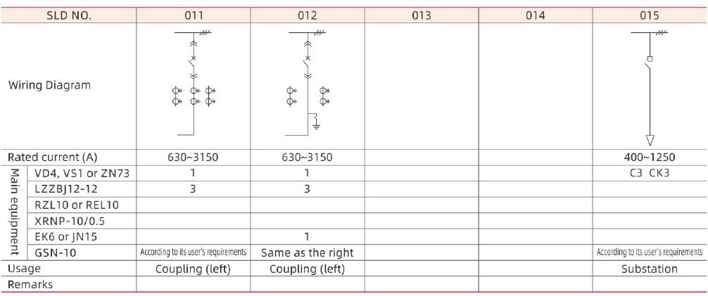
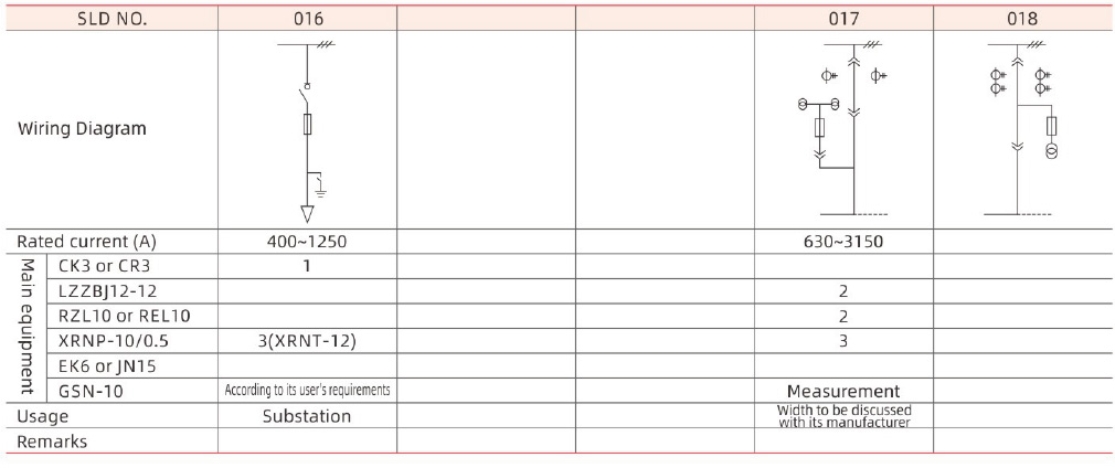
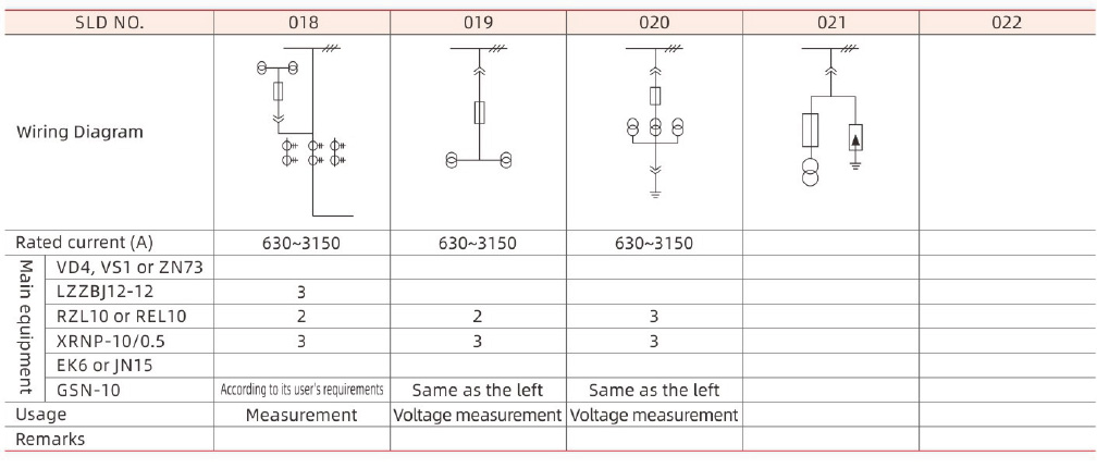
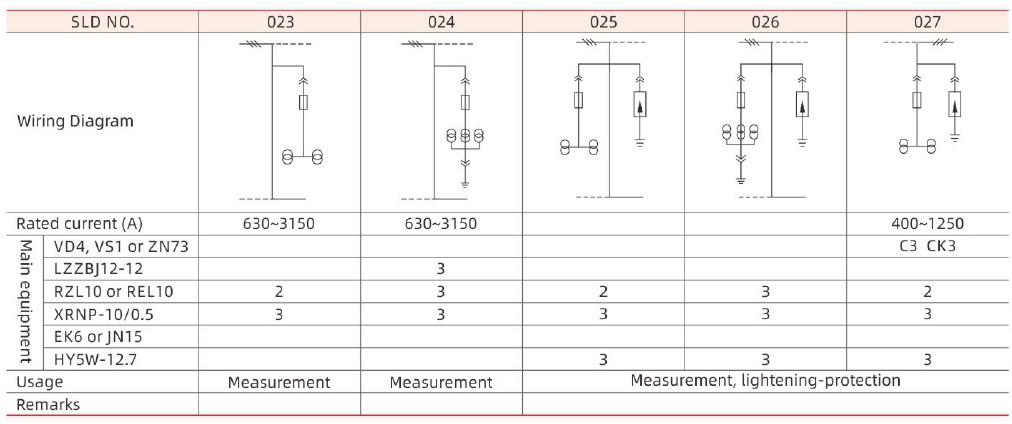
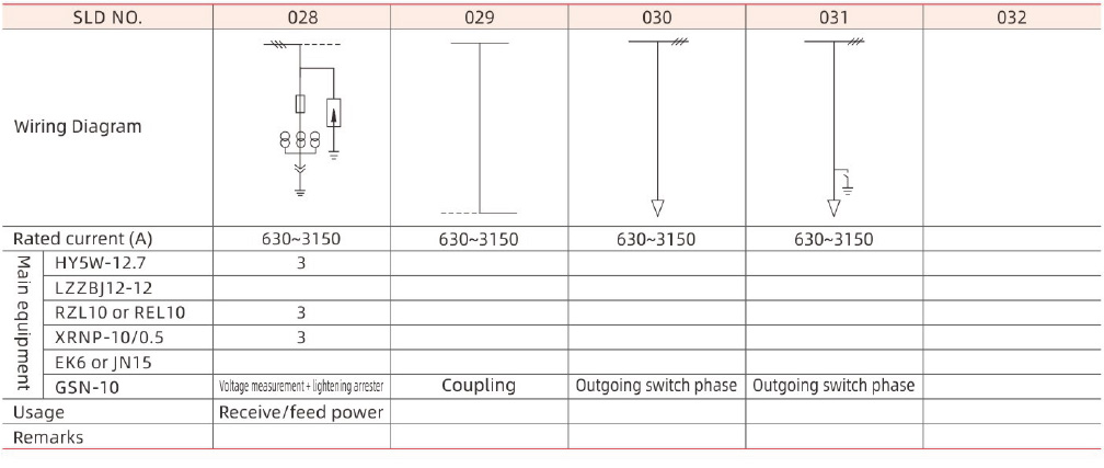
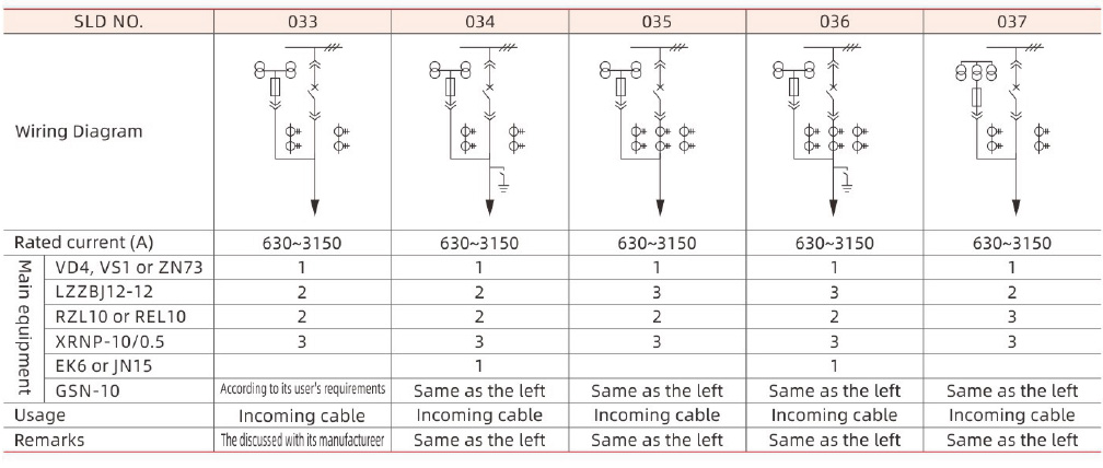
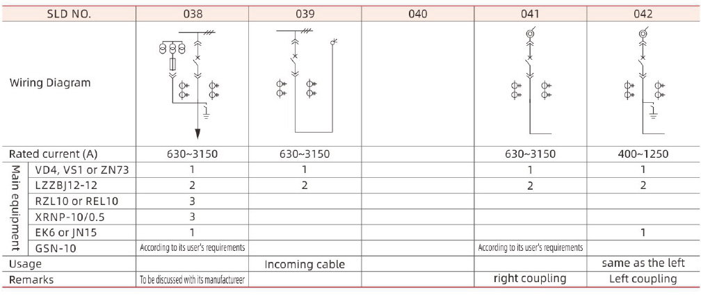
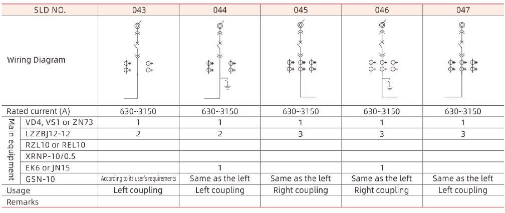
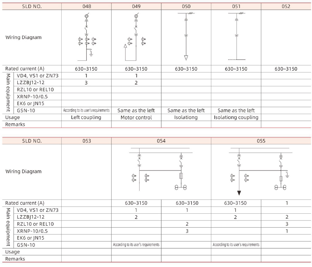
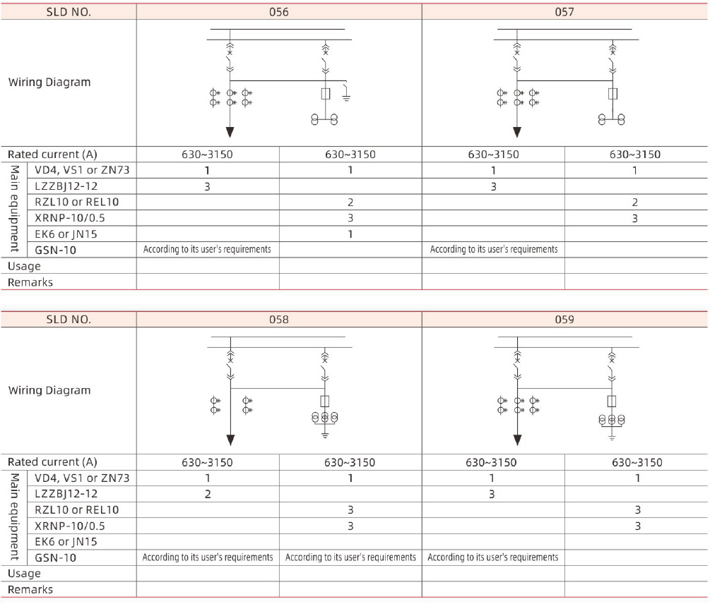
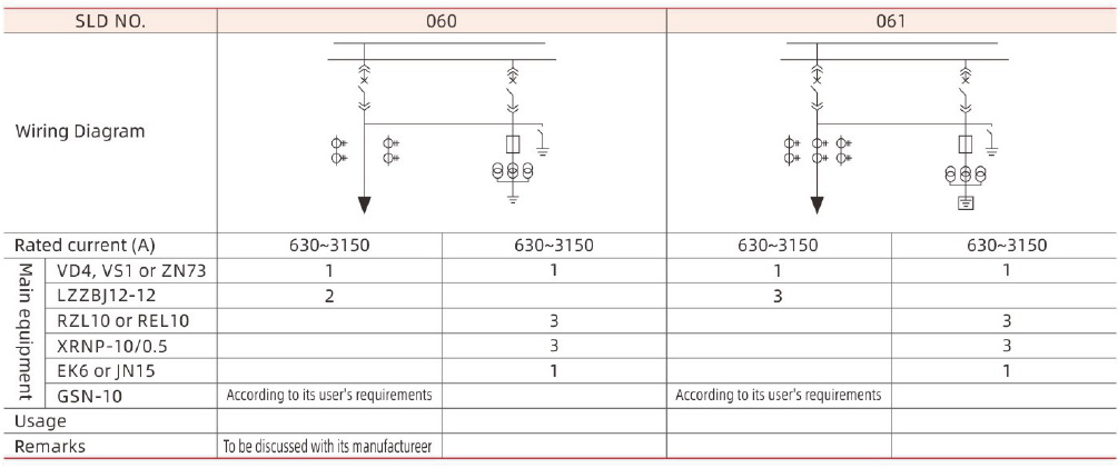
APPLICATION PROGRAMME:
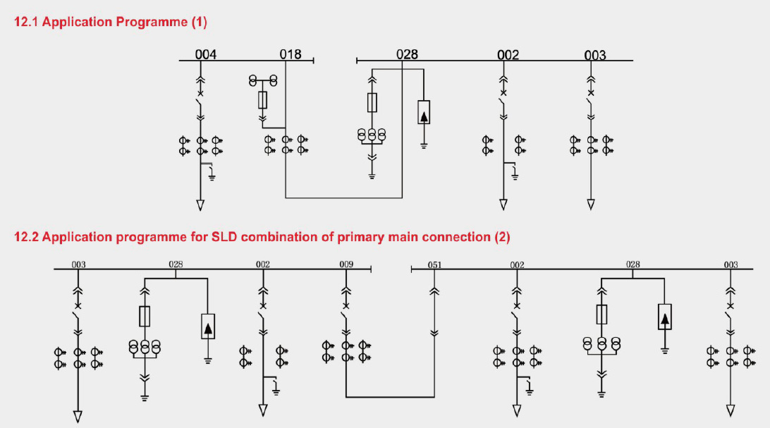 INSTRUCTION FOR ORDER:
User shall provide the following technical information as placing an order:
13.1 Main connection scheme number or system diagram, plan arrangement diagram of cubicles;
13.2 Secondary schematic diagram, terminal arrangement diagram. If without terminal arrangement diagram, it will be arranged by the manufacturer;
13.3 Model, specification and quality of components in the cubicle;
13.4 Provide cross-gap and height when the bus bridge is required;
13.5 Special service conditions shall be pointed out as ordering;
13.6 Make out the list of the required spare parts.




 ZHEJIANG DANHUA ELECTRIC
 E-MAIL:123569338@qq.com
 TEL:0577-27892288


 CN
CN
