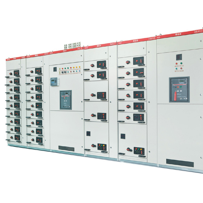
Product Ove rview:
MNS low-voltage switchgear is a kind of advanced low-voltage switchgear designed and improved by the company to meet the demand of market and the development of power industry. The product technical standards in line with GB7251 "Low-voltage switchgear and
control equipment" , international standard IEC61439, applicable to power plants, substations, petrochemical, metallurgical steel rolling,light Industry and textile enterprises and residential quarters, high-rise buildings and other places, as a 50Hz AC, rated working voltage AC 660V and below the distribution system power conversion, distribution and control purposes.
Product Features:
The cabinet structure used in MNS system is highly flexible, and once the structure is assembled, there is no need for maintenance.Different standard components can be installed in the cabinet to meet various requirements. Because the whole system, including
the electrical structure, is designed in combination, the optimized structure can meet the requirements of various components and different working environment, and reach the corresponding protection level.
Compact design:
More units installed in a narrow space.
Versatility in structure design and flexibility in assembly:
The C sheet steel with 25mm modular interval can meet the needs of different structural types, protection degrees, and service conditions.
The standard modules can make up standard units:
For protection, operating, switching, controlling, regulating, measuring and indication, The user can choose the relevant standard units for assembly according to requeirement.
More than 200 of structure parts and functional modules make it possible to make up different schematic requirements.
Due to high technical characeristics:
The main parameters reach international advanced level.
Reduction in space:
For storing and transporting per-fabricated parts thanks to the high degree of seriation, stander dization and generalization of the structure.
Easy assembly:
No special tools needed.
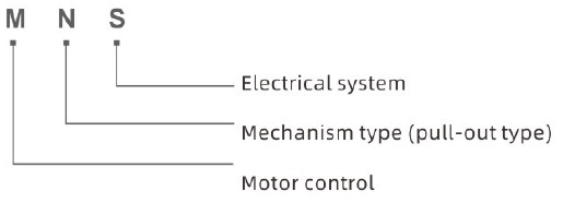
Meaning of the model:
 Service conditions:
Ambient temperature: Upper limit +40°C, Lower limit -25°C
Humidity: The average relative humidity measured within 24 hours did not exceed 95% ;
The average water vapor pressure measured within 24 hours shall not exceed 2.2 kpa;
The monthly relative humidity value does not exceed 90% ;
The average monthly water vapor pressure does not exceed 1.8kpa;
Altitude:书2000m
Earthquake intensity: $ 8 degrees
Level of filth: Level 3
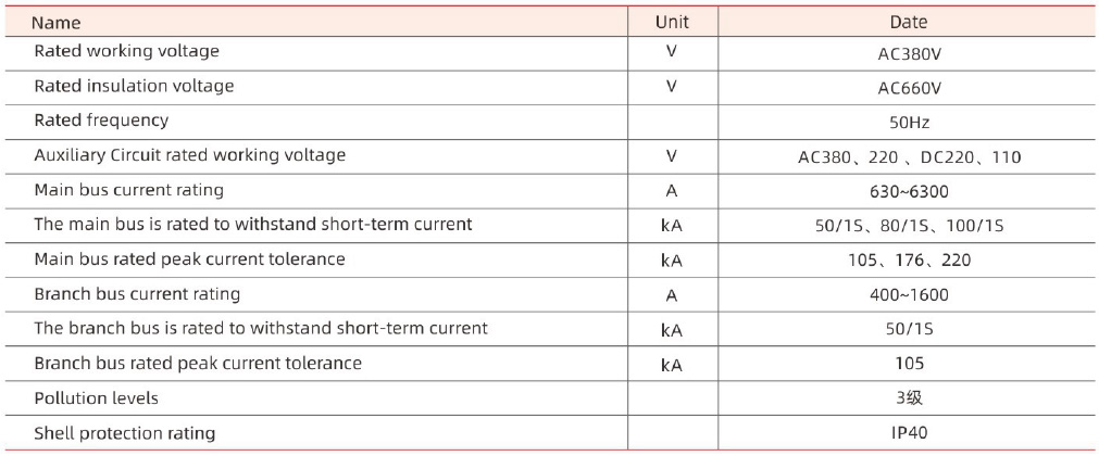
Rated parameters of switchgear:
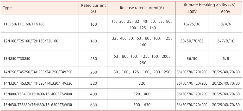
 Technical parameters of primary circuit electrical equipment:
TMAX series plastic shell type high break type circuit breaker
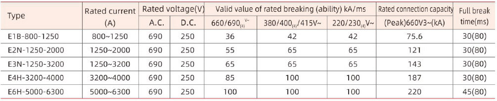
Emax Series low voltage air circuit breaker
TA series thermal relay
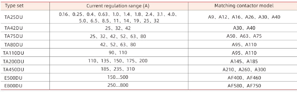
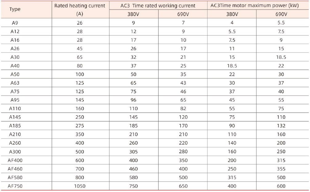
A~ AF series AC contactor
 Product Features:
The basic frame of the device is an assembled structure. All the components of the frame are galvanized and connected to each other by self-ta pping locking screws or grade 8.8 hexagonal screws to form the basic frame, together with the corresponding doors, seals,partitions, mounting brackets, as well as the Busbar, function unit and other components, assembled into a complete device, device parts scale, the dimension of the partition is modularized (modulo unit is e = 25mm, same as below)
Power distribution center (hereinafter referred toas PC):
The PC cabinet is divided into four compartments
Horizontal bus compartment: at the back of the cabinet
Function unit compartment: in front of the upper cabinet or cabinet before the left
Cable compartment: at the lower part of the front of the cabinet or the right of the front of the cabinet
Control circuit compartment: in front of the upper cabinet
Segregation measures
・Level bus compartment and functional unit compartment, cable unit compartment between melamine phenolic sandwich or steel plate separation.
・The control circuit compartment and the functional unit compartment are separated by a flame-retardant polyurethane foam molded housing.
・The function unit compartment on the left and the cable compartment on the right are separated by steel plates.
・The frame type circuit breaker installed in the cabinet can be operated manually in the cabinet when the door is closed, determine whether the circuit breaker is in the test position or in the working position.
・The separation structure between the main circuit and the auxiliary circuit is designed, and the auxiliary circuit unit composed of the instrument, the signal lamp and the button is installed on the plastic board, a cover made of flame-retardant polyurethane foamed plastic is separated from the main circuit at the back of the plate.
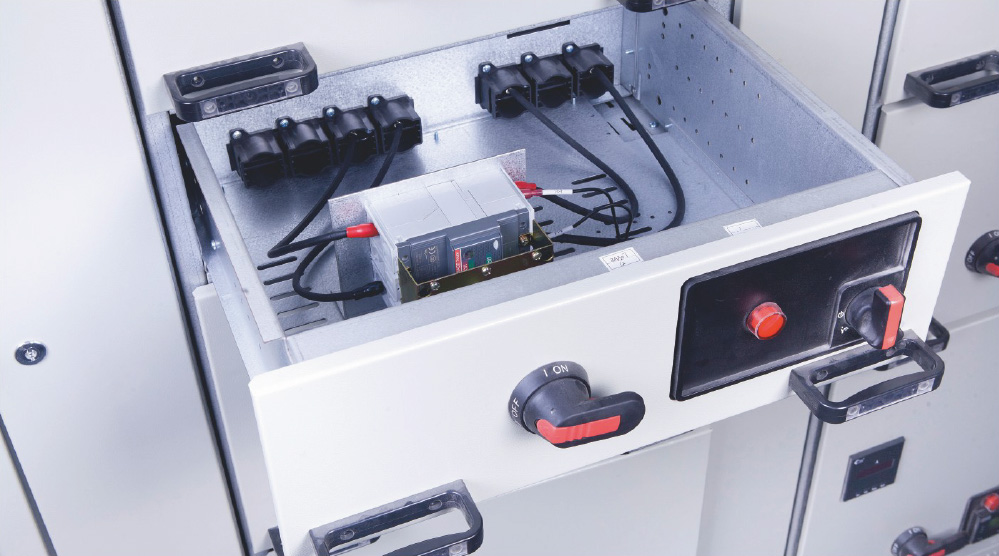
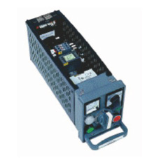
Pull-out motor control center and small current power distribution center (hereinafter referred to as pull-out MCC)
・The MCC cabinet is divided into three compartments, i. e. the horizontal compartment at the back of the cabinet, the functional unit compartment on the left of the front of the cabinet, and the cable compartment on the right of the front of the cabinet. The function partition between the horizontal bus compartment and the function unit compartment is made of flame-retardant polyurethane foam, and the steel plate is used to separate the cable compartment and the horizontal bus compartment and the function unit compartment.
・The draw-out MCC has two structures: single-side operation and double-side operation.
・The draw-out Type MCC has five standard size drawers: 8e/4,8e/2,8E and 16E and 24E. The structure of 8E/4,8e/2 drawers consists of molded flame-retardant plastic parts and aluminum profiles. 48E/4 drawers and 28e height intervals. The total height of the functional unit compartment is 72E.
・Five standard size drawers, generally have 16 secondary isolation contact leads, if necessary, in addition to 8E4 drawer, the other four drawers can be increased to 32. Each static contact terminal can be connected to three wires at the same time. (two are connected with type TT1-205/2.8X0.8 socket terminal and the other one is connected with type 1T2.5-2 pin terminal, both of which are supplied by cold-rolled pliers with appropriate accessories.)
・Through the operating procedure of the mechanical interlocking device, the drawer can only be moved when the main circuit is completely disconnected. The mechanical interlocking device makes the drawer have a moving position, a test position and a segment position,connect and detach positions and mark them with corresponding symbols.
Portable motor control center and small current power distribution center (hereinafter referred to as mobile MCC)
・The structural characteristics of movable MCC are copper 5.2.1 and copper 5.2.2.
・The function unit can be designed as a movable structure, the function is single to connect with the vertical bus, and the primary isolation contact is adopted, even if the circuit connected with it is electrified, the unit can be taken out and put back in its entirety from the equipment, and the other end is a fixed structure.
・The functional units of the portable MCC are divided into 3E, 6E, 8E, 16E, 24E, 32E, 40E, and the total height of the functional unit compartment is 72E.
Bus System
・The horizontal bus bar is installed in the independent bus bar compartment behind the cabinet. It has two alternative installation positions, i. e. one third or two thirds of the cabinet height, ye can be installed up and down at the same time, two groups of buses can be used alone, ye can be used in parallel, not parallel with the bus by two or four or eight buses, bus cross- sections of 10x30x20,10x60x2,10x80x2, 10x60x4, 10x80x2x2 and 10x60x4x2(mm)
・The vertical bus bar is a 50X50X5 angle ruler copper bus bar, which is embedded in the functional wall made of flame-retardant plastics. Protection of live parts up to IP20.
・Neutral Busbar (N) and neutral protection busbar (PE or PEN) neutral busbar and neutral protection busbar are installed parallel in the lower part of the function unit compartment and vertically in the cable compartment, if the insulator is used to separate the N-line from the PE-line, then the N-line and the PE-line are used respectively. If the conductor is used to short the n-line and the PE-line, the PEN-line isformed.
Protect the grounding system
The protection circuit of the device consists of two parts: PE line (or PEN line) and conductive structure which are installed separately and run through the whole arrangement length. The metal structural parts in the device, except the exterior door and seal plate, are all galvanized, and the joints of the structural parts are carefully designed so that they can pass a certain short-circuit current.
Auxiliary circuit cable slot
An auiliary circuit cable groove is arranged on the top of the function unit compartment. The connecting wires between cabinets and common power supply wires can be arranged in the groove
Isolation Measures for auxiliary circuits
In each circuit of the draw-out MCC scheme, an isolation transformer may be installed according to the system requirements. The transformer capacity is determined according to the AC contactor provisions, as shown in the table below.
Standard component solutions
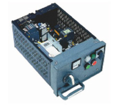
 8E/4 Pull-out components
Fuse core switch or molded case circuit breaker for distribution
Motor starter with fuse
Motor starter with molded case circuit breaker
Motor starter with M101, M102 motor control and protection device
Component specifications: 8E/4,8e/2,8E, 16E, 24E.
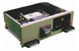
8E/4, 8E/2 Pull-out components
 8E/2 Pull-out components
The 8E/4 and 8E/pull-out modular structures include an instrument panel, an insulating side panel, a rear panel with cable terminals, and one or two 16-Core control wire terminal mounting pieces. According to different requirements 8E/2 can be equipped with two 16-core terminals.
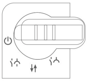
The instrument panel is provided with a knock-down hole for mounting a measuring, operating and displaying device. The operation of the main switch is accomplished by a handle mounted on the instrumentpanel. The handle has electrical and mechanical interlock function.Electrical interlock is accomplished by a fretting switch with one normally open and one normally closed contact.
After the operation handle is pressed inward, it can move from 0 position to I position. The padlock can be added to the main switch on the operating handle to open the gate, test and isolate three positions for safety protection, up to 3 locks can be added.
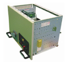
8E, 16E , 24E Pull-out components
 8E Pull-out components
The 8E to 24E pull-out assemblies include an instrument panel, an insulated rear panel, a front cover, a metal side panel, and a wiring groove
The hinged subassembly door facilitates the replacement of components from the front, such as fuses, without the need to pull out the subassembly.When the unit is in working and testing position, the front door can only be opened with a tool (e. g. Screwdriver, Double Lock) . Double locks are available when components are in an isolated position.
8E, 16E , 24E Pull-out components
 16E Pull-out components
The front cover plate is provided with an opening for mounting the instrument panel, and the instrument panel is opened on the front cover plate and left in place when closed. The instrument panel is provided with knock- down holes for mounting metering, operating and indicating devices. The operation handle has the function of electrical and mechanical interlock. The electric interlock is accom- plished by a fretting switch with one normally open and one normally closed contact.
Switch Handle Position Description
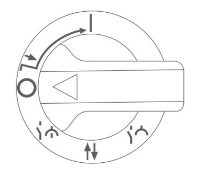 Switch handle
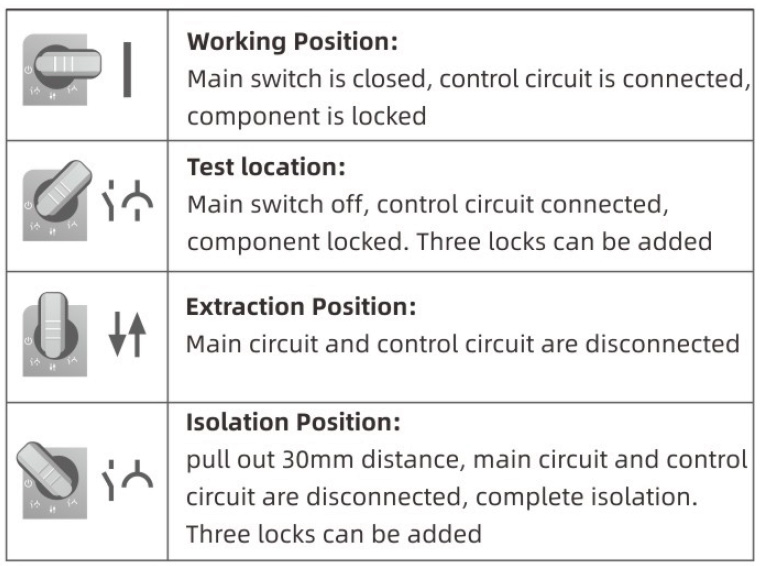
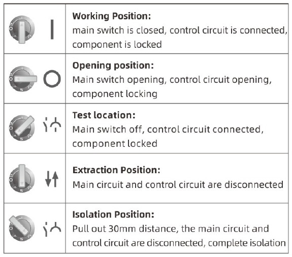 Out-of-the-box component operation handle position description
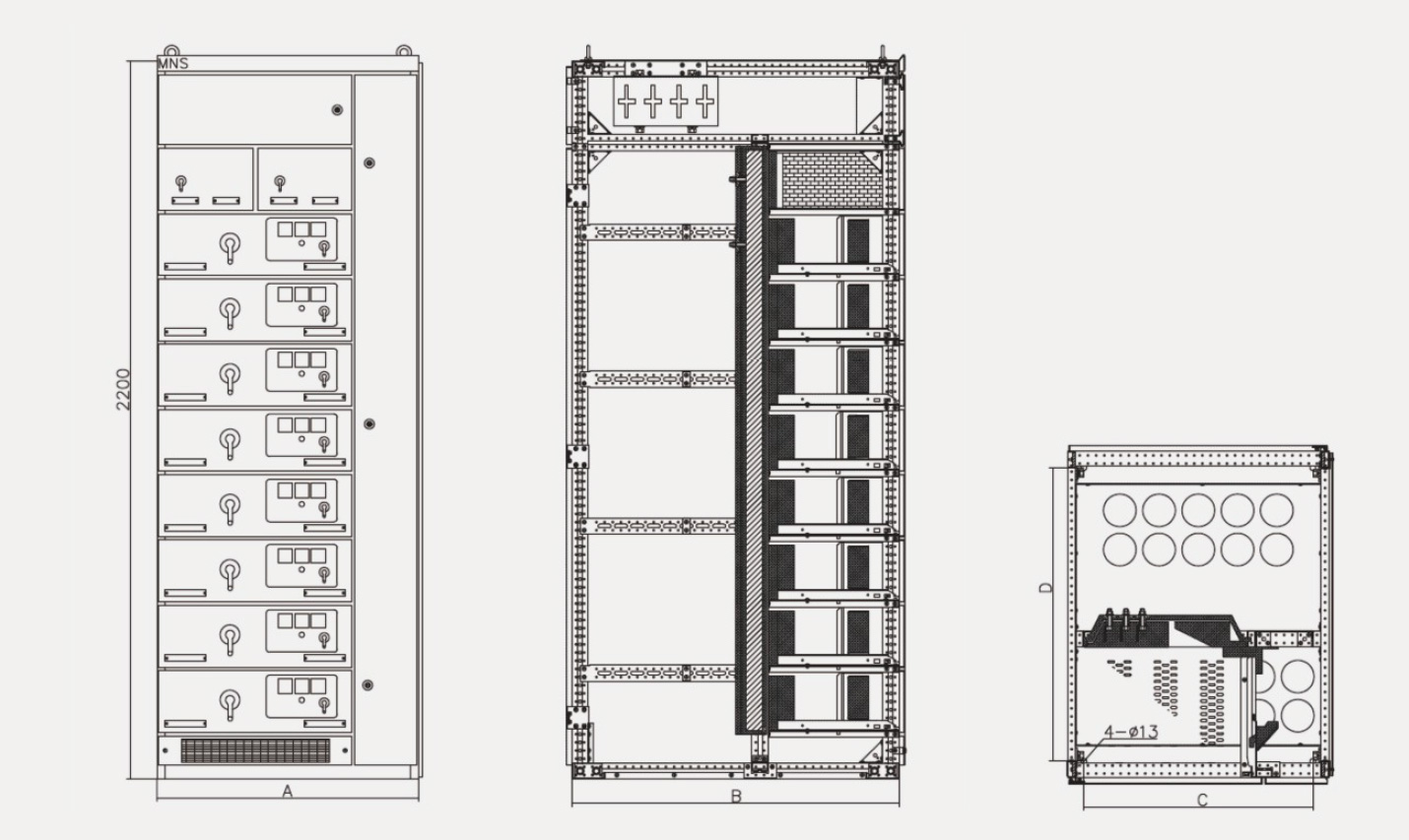
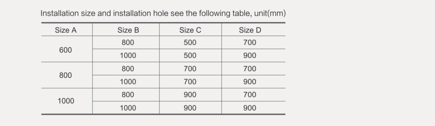
 External dimensions:
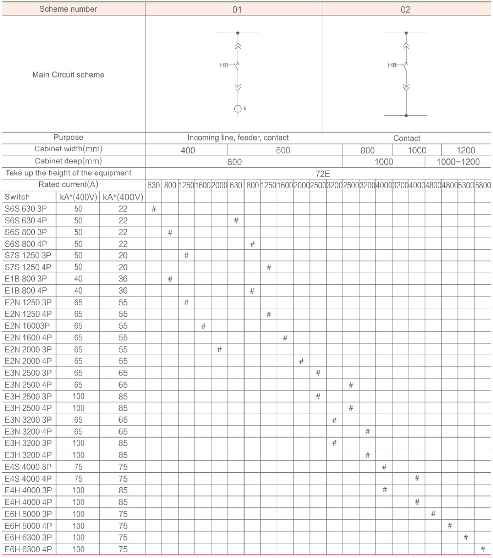
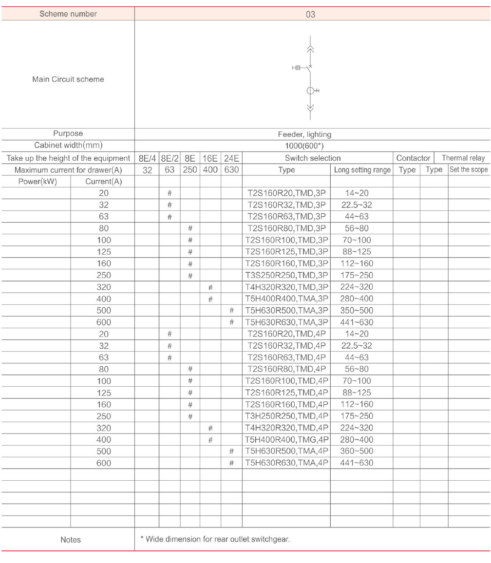
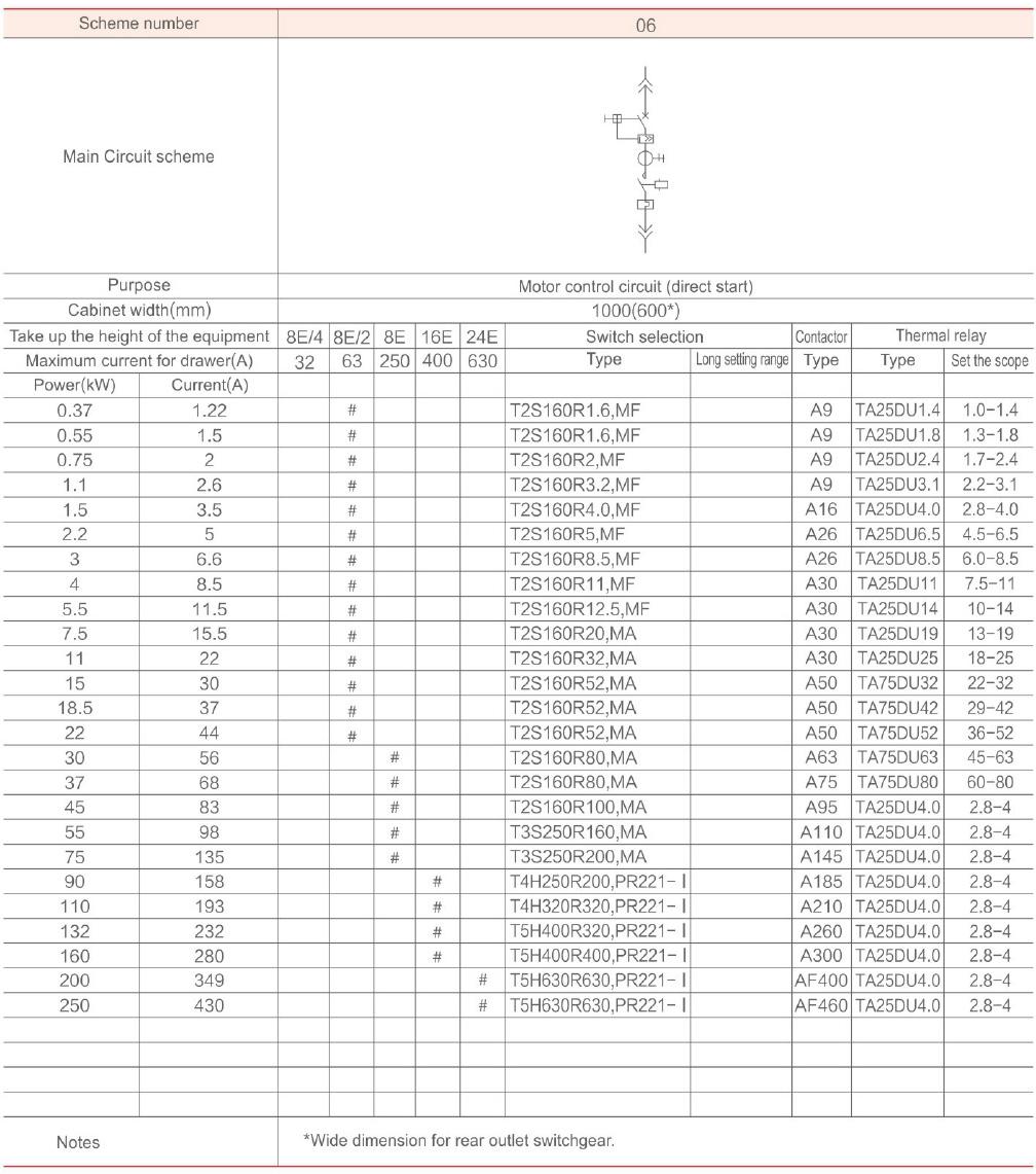
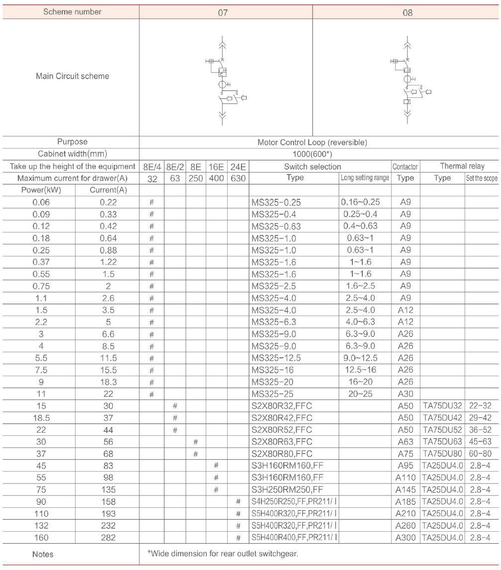
 Typical scenario:
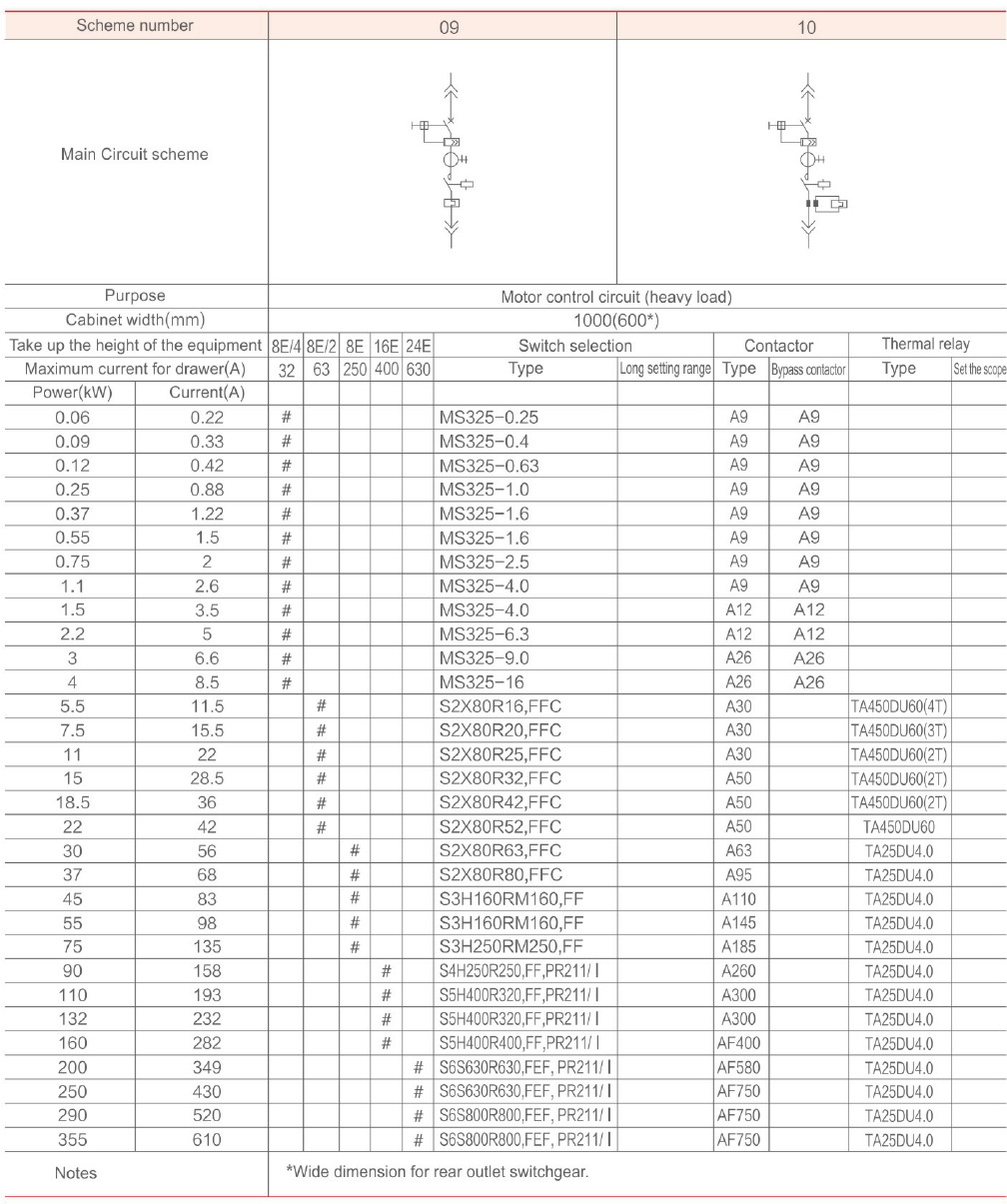
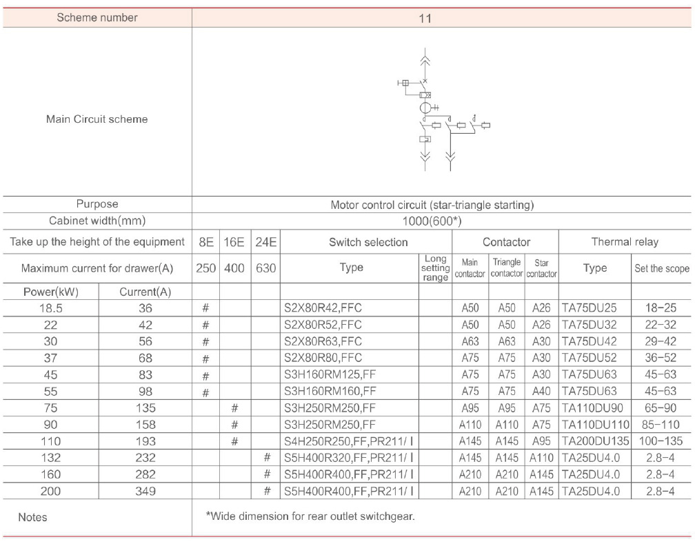
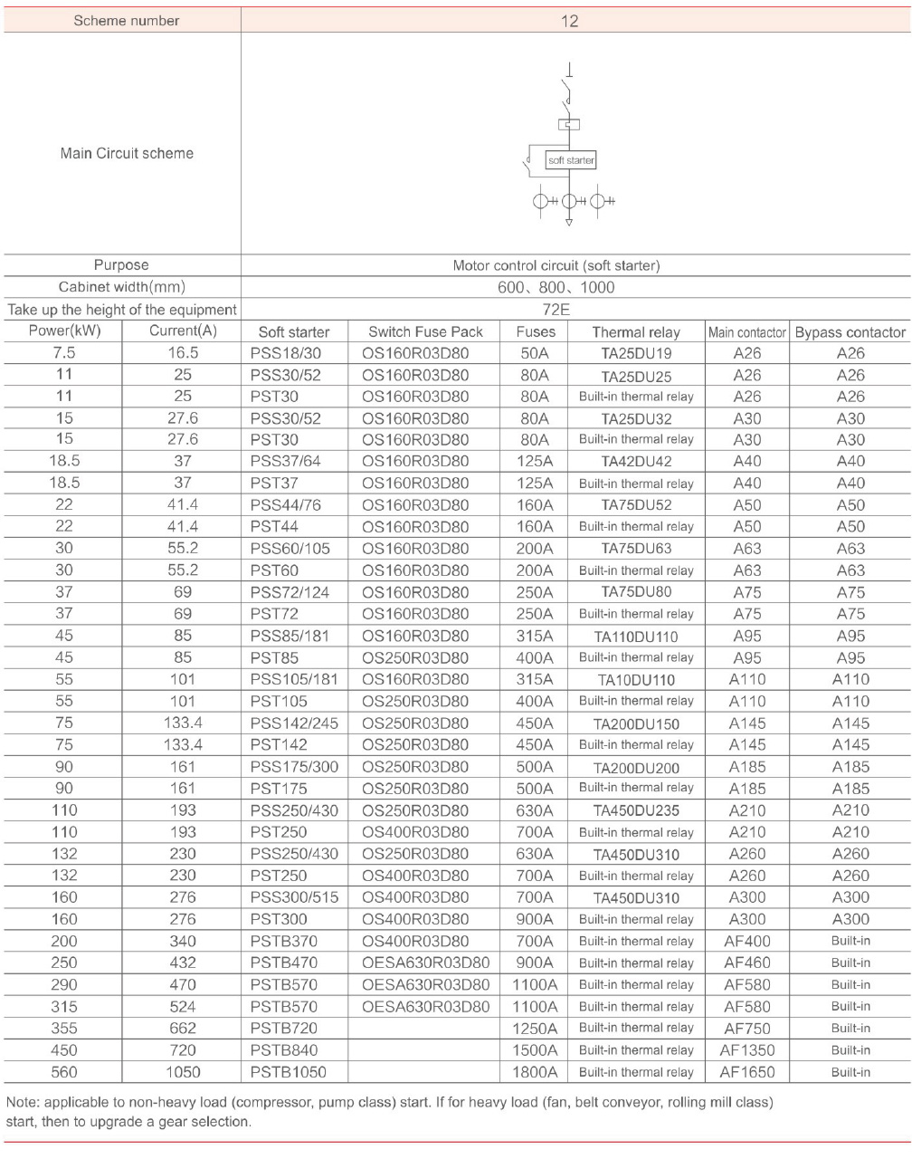
The typical scheme of switchgear is shown in the one-time scheme table. For the one-time combination scheme not listed in the table, please consult us.
Pull-out structure 380V 50Hz 50KA system

 A145 pull-out structure 380V 50Hz 50KA system

 ZHEJIANG DANHUA ELECTRIC
 E-MAIL:123569338@qq.com
 TEL:0577-27892288
 CN
CN