Your location:
Home ->
Products -> Low voltage switchgear series
Product overview:
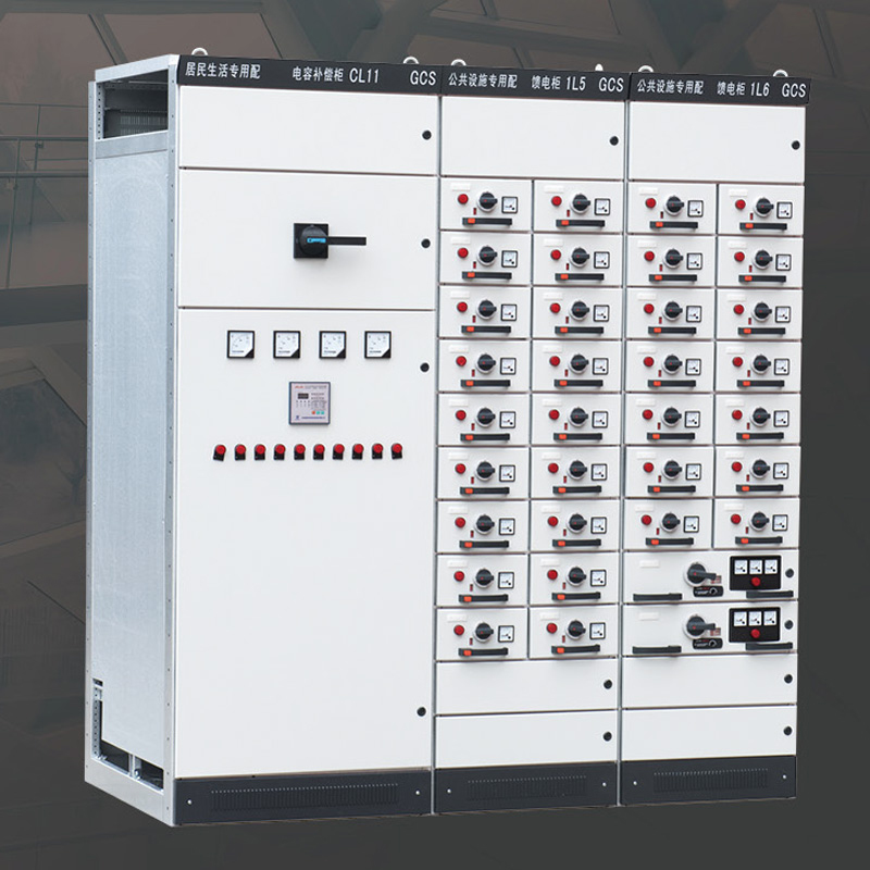
GCS devices are suitable for distribution systems in industries such as power plants, petroleum, chemical, metallurgical, textile,and high-rise buildings. In places with high automation levels such as large power plants and petrochemical systems that require computer interfaces, low-voltage complete distribution devices are used for distribution, centralized control of electric motors,and reactive power compensation in power generation and supply systems with a three-phase AC frequency of 50 (60) Hz, rated working voltage of 380V (400V), (660V), and rated current of 4000A and below.
Model and meaning:
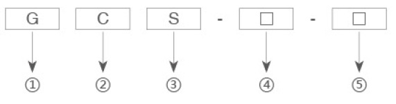
①Enclosed switch cabinet
②Draw out type
③Electric system
④Main circuit solution number
⑤Auxiliary circuit solution number
Performance index
The design of the device meets the following standards:
◇IEC439-1 Low voltage complete switchgear and control equipment
◇GB 7251 Low Voltage Complete Switchgear
◇ZBK 36001 low-voltage withdrawable complete switchgear
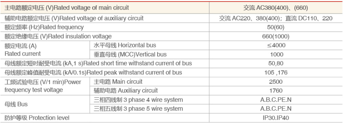
Technical parameter
 装置特点Device feature
◇Improve the heat capacity of the adapter, and greatly reduce the additional temperature rise caused by the temperature rise of the adapter to the connectors, cable logs and spacers.
◇The separation between functional units and compartments is clear and reliable, and the failure of one unit will not affect the work of other units so as to minimize the failure.
◇The horizontal arrangement of the bus bar makes the device have good dynamic and thermal stability, and can withstand the impact of 80/1 76kA short-circuit current.
◇The number of circuits in a single MCC switchgear is as many as 22, which fully considers the needs of large single-unit power generation, petrochemical systems and other industries for automated motor groups.
◇The connection between the device and the external cable is completed in the cable compartment, and the cables can be entered and exited up and down. The current transformer is installed in the cable compartment to facilitate installation and maintenance.
◇The same power distribution system can limit the short-circuit current through the matching of current-limiting reactors, stabilize the bus voltage at a certain value, and partially reduce the short-circuit strength requirements of the components.
◇The drawer unit has a sufficient number of secondary connectors (32 pairs for 1 unit and above, 20 pairs for 1/2 unit), which can meet the requirements of the number of computer interfaces and automatic control circuits.
Auxiliary circuit
The design of the auxiliary circuit diagram conforms to the "Technical Regulations for the Design of Auxiliary Power for Thermal Power Plants" and other relevant design technical regulations. It is applicable to the low-voltage power system of power plants and substations and the low-voltage power distribution systems in factories and mining enterprises and high-rise buildings.
The auxiliary circuit solution is designed according to the main circuit solutions, which features the functional units of the power supply cable, the feeder (PC) and the motor feeder (MCC) for operation control.
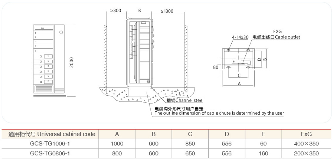
Installation diagram
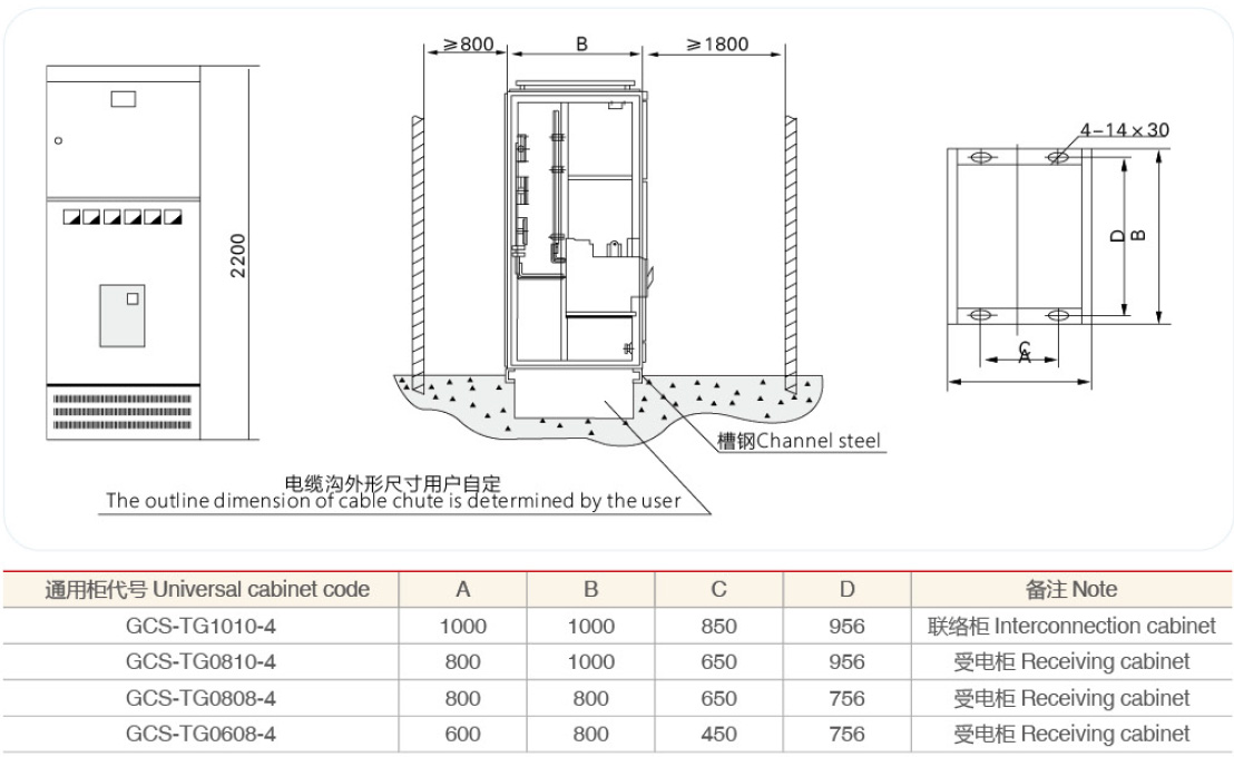
Fig. 2 PC cabinet installation diagram
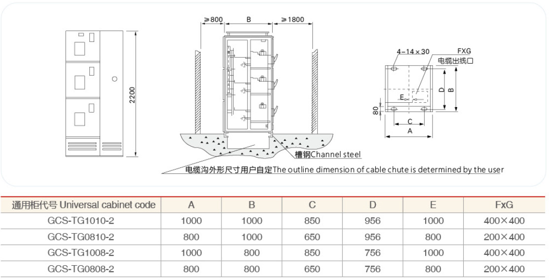 Fig.3 MCC cabinet installation diagram
 Ordering instruction:
The order contract includes the following contents:
◇The full model of the product includes the main circuit solution number and auxiliary circuit solution number
◇ Main circuit system combination sequence diagram Auxiliary circuit schematic diagram
◇ List of components in the cabinet
◇Voltage, current, time and other setting parameters in the circuit
◇Other special requirements inconsistent with the normal use of the product
 ZHEJIANG DANHUA ELECTRIC
 E-MAIL:123569338@qq.com
 TEL:0577-27892288
 CN
CN