Your location:
Home ->
Products -> High voltage switchgear series
Product overview:
XGN66-12 box type fixed closed switchgear (hereinafter referred to as switchgear) is suitable for 3.6~12kV three-phase AC 50Hz system as the device to receive and distribute electric energy, it' s used for frequent operation places and for reconstruction of switchgear equipped with oil switch.The bus system consists of single bus system and single bus section system.
Model and meaning:

①Box structure
②Fixed type
③Indoor
④Design No.
⑤(kV) Rated voltage
⑥Main circuit solution number
Service condition:
◇Ambient temperature: maximum +40°C,minimum-15°C ;
◇Altitude: not more than 1000m;
◇Relative humidity: daily average no more than 95%, monthly average no more than 90%;
◇Earthquake magnitude: 8 or less;
◇In place of no fire or explosion risk, no serious pollution, no chemical corrosion and no violent vibration.
Product structure:
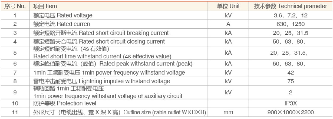
◇Schematic diagram for switchgear (Figure 1)
◇The switchgear is a box-type fixed structure, and the switchgear body is welded by thin plates and angle iron. The upper part of the rear of the switchgear is the main bus compartment, and the top of the compartment is equipped with a pressure release device; the upper part of the front is a relay compartment, and the small bus can be connected from the bottom of the compartment with a cable. The middle and lower parts of the switchgear are connected. The bus compartment is electrically connected to the middle and lower part through the GN30 rotary isolating switch; the middle part is installed with a vacuum circuit breaker, and the lower part is installed with a grounding switch or an outlet side isolating switch; the rear part is installed with a current transformer, a voltage transformer, and a lightning arrester. The primary cable exits from the lower part of the rear of the
switchgear; A grounding bus is arranged at the bottom of the switchgear, which runs through the entire row of switchgear; the isolation switch and the grounding switch are operated at the front left of the switchgear.
◇The switchgear adopts the corresponding mechanical locking device, the locking structure is simple, the operation is convenient, and the five preventions are reliable.
◇ Only after the circuit breaker is actually disconnected, the handle can be pulled out from the "working" position and turned right to the "disconnecting" locking position to open and close the isolating switch, which prevents the opening and closing of the isolating switch from being loaded.
◇ When the circuit breaker and the upper and lower isolation are in the closed state and the handle is in the "working position",the front switchgear door cannot be opened to prevent accidental entry into the live compartment.
◇When the circuit breaker and the upper and lower isolating switches are both in the closed state, the handle cannot be turned to the "Maintenance" or "breaking lock" position to avoid accidental opening of the circuit breaker. When the handle is at the "breaking lock" position, with only separate the upper and lower isolation, however, the circuit breaker cannot be closed, avoiding the mistaken closing of the circuit breaker.
◇When the upper and lower isolation is not opened, the grounding switch cannot be closed, and the handle cannot be rotated from the "disconnecting and locking" position to the "inspection" position, which can prevent the live ground wire from being hooked.
Note: According to different switchgear solution, some solutions do not have the lower isolation, or the lower isolation is replaced by a grounding switch, and the lockout and five preventions can meet the requirements.
Technical parameter:
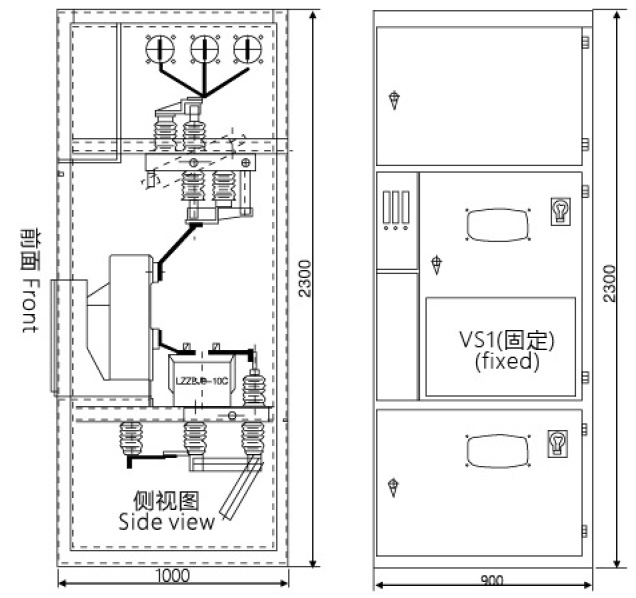
 Installation size and basic diagram:
◇Refer to Figure (2) for the installation foundation, the foundation channel steel protrudes 1-3mm from the ground, the unevenness per meter should not exceed 1.5mm, and the full length should not exceed 5mm.
◇ Place the switchgear on the foundation in order and adjust the installation position. Then fix it with M12 bolts or spot welding, and tighten the switchgear with M8 bolts.
◇After disassembling the cover plate to install the main bus and primary cables, the contact surface of the terminals should be cleaned and coated with neutral petroleum jelly. After installation, please block the primary cable hole.
◇ Connect the indirect ground bus bar of the switchgear to make it into one body along the arrangement direction of the switchgear. Check whether the grounding is missing, whether the grounding loop is continuous, and the grounding resistance should not be greater than 10.
◇Install the secondary cable. The cable is introduced from the botom of the front of the switchgear, enters the relay room along the side wall, and is tapped on the terminal block; after installation, the cable hole should be blocked.
◇Clean up the dust and debris inside the switchgear.
 Delivery information:
The manufacturer shall provide the following documents and attachments when supplying:
◇ Shipping list;
◇ Product qualification certificate and factory test report;
◇ User manual;
◇ Relevant electrical drawings;
◇ Main components manual;
◇ Cabinet door key, operating handle and spare parts specified in the contract.
Switch cabinet outline size:
 Ordering instruction:
◇ Primary wiring solution diagram and primary wiring solution arrangement diagram.
◇ Secondary circuit schematic diagram, wiring diagram, terminal wiring diagram.
◇ List of primary and secondary equipment.
◇ Switch cabinet layout and bus and cable tray location.
◇ Please negotiate with our company for any special service condition of spart part and equipment.
 ZHEJIANG DANHUA ELECTRIC
 E-MAIL:123569338@qq.com
 TEL:0577-27892288
 CN
CN